top of page

SENSORS
Photoelectronic Sensors
Distance Measurement
Triangulation


P3 Series: Laser Precision with Smart Operating Concept

PNBC Series: Real-Time Measurement in the Micrometer Range


Non-Contact Measurement with Light


Temperature Sensors for Contactless Measurement
Temperature Sensors for Contactless Measurement


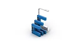


Fiber-Optic Sensors
Fiber-Optic Amplifiers

Fiber-Optic Amplifiers
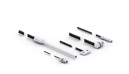
Fiber-Optic Amplifiers

Fiber-Optic Amplifiers


Light Curtains
Light Curtains Pick-to-Light
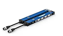
Light Curtains for Measuring Tasks

Retro-Reflex Sensors with Light Band
Retro-Reflex Sensors with Light Band
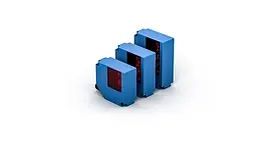
Sensors for Roller Conveyor Systems
Reflex Sensors with Background Suppression

Retro-Reflex Sensors

Logic Units

Contrast Sensors
Contrast Sensors with Laser Light

Contrast Sensors with White Light



Luminescence Sensors
Luminescence Sensors
Gloss Sensors
Gloss Sensors


Dynamic distance measurement and dynamic positioning


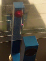

With many applications it is essential to determine distances, e.g. the distance between two objects (gap size measurement) during a movement. The sensors of the A-LAS series or the SPECTRO-1-CONLAS series and the SPECTRO-2-CONLAS series perform very good services and can provide scan frequencies of up to 175 kHz. The measurement ranges are determined by the light spot size. Spot sizes from 0.1mm to 100mm are available.
Fibre optics cross-section converters can be used in potentially explosive atmospheres. The longitudinal axis of the right-angled cross-section determines the size of the measurement range. The SPECTRO-1-FIO and SPECTRO-2-FIO sensors are two quick versions for potentially explosive atmospheres with scanning frequencies up to 175 kHz or 130 kHz.
What is a Photoelectronic Sensor?
A photoelectronic sensor is a non-contact sensor that uses light to detect the presence, position or movement of an object. The sensor transmits a beam of visible, infrared or laser light and detects changes in the received light when an object enters the sensing area. Photoelectronic sensors are widely used in industrial automation for object detection, counting, positioning, conveyor monitoring and process control.
Common types include:
-
through-beam sensor
-
retro-reflective sensor
-
diffuse-reflective sensor
What is a Through-Beam Sensor?
A through-beam sensor is a photoelectric sensor consisting of a separate transmitter and receiver positioned opposite each other. The transmitter projects a beam of light directly to the receiver, and an object is detected when it passes between them and interrupts the beam. Through-beam sensors provide reliable, long-range object detection and are commonly used for counting, positioning, conveyor monitoring and industrial automation applications.
How through-beam sensors work
Transmitter → Object → Receiver
Under normal conditions, the receiver continuously detects the light from the transmitter. When an object blocks the beam, the receiver registers the interruption and switches its output.
Because the light travels directly from the transmitter to the receiver rather than relying on light reflected from the target, through-beam sensors generally offer:
-
Long sensing ranges
-
High detection reliability
-
Fast response times
-
Reliable detection of small or fast-moving objects
-
Reduced dependence on the object's colour, surface or reflectivity
-
Good performance in demanding industrial environments
Typical applications include conveyor monitoring, object counting, packaging machinery, component detection, position control, production-line monitoring and machine safety applications. For safety applications, however, the sensor/system must have the appropriate safety certification.
What is a Retro-Reflective Sensor?
A retro-reflective sensor is a photoelectric sensor that contains both the light transmitter and receiver in a single housing and uses a separate reflector to return the emitted light. When an object passes between the sensor and reflector, it interrupts the returned light beam and causes the sensor to switch its output. Retro-reflective sensors provide reliable object detection over relatively long distances while requiring electrical wiring on only one side of the detection area.
The sensor projects a beam of visible, infrared or laser light toward the reflector. The reflector returns the light to the sensor's receiver. When an object passes between the sensor and reflector and interrupts or reduces the returned light, the sensor detects the object and generates an electrical output signal to a PLC, controller or automation system.
How a retro-reflective sensor works
Sensor (Transmitter + Receiver) → Object → Reflector
Compared with a through-beam sensor, only one powered sensor unit needs to be wired, making installation simpler while still allowing relatively long sensing distances.
Many modern retro-reflective sensors also use polarised light, which helps prevent false detection from shiny or reflective objects.
Typical applications include conveyor systems, packaging machinery, object counting, material handling, production lines, door and gate detection, and general industrial automation.
What is a Diffuse-Reflective Sensor?
A diffuse-reflective sensor is a photoelectric sensor that contains both the light transmitter and receiver in a single housing and detects light reflected directly from the target object. Unlike a retro-reflective sensor, no separate reflector is required. When an object enters the sensing range, light reflected from its surface is detected by the receiver, causing the sensor to switch its output. Diffuse-reflective sensors are commonly used for object detection, positioning, counting and conveyor monitoring in industrial automation.
The sensor projects visible, infrared or laser light towards the target object. Some of this light is reflected from the object's surface back to the sensor's receiver. When sufficient reflected light is detected, the sensor switches its output and sends a signal to a PLC, controller or automation system.
How a diffuse-reflective sensor works
Sensor (Transmitter + Receiver) → Object → Light reflected back to Sensor
Because the object itself acts as the reflector, detection can be affected by the object's colour, surface finish, material, angle and reflectivity. Dark or matt objects generally reflect less light than bright or highly reflective surfaces.
More advanced diffuse-reflective sensors use background suppression or distance measurement to distinguish the target from objects or surfaces behind it.
Typical applications include object detection, component positioning, conveyor monitoring, counting, packaging machinery, presence detection and general industrial automation.
How does a retro-reflective sensor and a diffuse-reflective sensor differ?
The presence or absence of a separate reflector is the key distinction.
A retro-reflective sensor contains both the light transmitter and receiver in a single housing and uses a separate reflector to return the emitted light.
A diffuse-reflective sensor contains both the light transmitter and receiver in a single housing and detects light reflected directly from the target object.
What is a Laser Distance Sensor that uses Triangulation?
A laser triangulation distance sensor is a non-contact optical sensor used for precise measurement of distance, position and displacement. The sensor projects a laser beam onto a target and measures the position of the reflected light on an internal optical detector. Using the principle of triangulation, it calculates the exact distance to the target. Laser triangulation sensors provide high-resolution measurements and are widely used for positioning, thickness measurement, surface inspection, quality control and precision measurement in industrial automation.
The sensor projects a laser spot onto the target surface. Light reflected from the target is received by an optical detector inside the sensor. As the target moves closer to or further away from the sensor, the position of the reflected light on the detector changes. Using the known geometry between the laser source, target and detector, the sensor calculates the distance to the object.
How laser triangulation works
Laser emitter → Target → Reflected light → Optical receiver
The laser and receiver are positioned at a known angle to one another. Changes in the target distance alter the angle at which the reflected laser reaches the receiver. The sensor converts this change into a precise distance measurement.
Laser triangulation sensors are particularly suited to short- and medium-range, high-precision measurements, often where very small changes in position need to be detected.
Typical applications include:
-
Distance and position measurement
-
Thickness and height measurement
-
Displacement measurement
-
Part positioning and alignment
-
Surface and profile measurement
-
Quality inspection
-
Diameter measurement
-
Production and assembly-line monitoring
-
Robotics and automated handling
What is a Laser Distance Sensor that uses Time-of-Flight (ToF)?
A Laser Time-of-Flight (ToF) Distance Sensor is a non-contact optical sensor that measures the distance to an object using laser light. The sensor emits a laser signal towards the target and measures the time taken, or corresponding phase shift, for the reflected light to return. Using the known speed of light, the sensor calculates the distance to the target. Time-of-Flight laser sensors are particularly suited to long-range distance and position measurement and are widely used in industrial automation, logistics, material handling, level measurement and machine positioning applications.
The sensor emits a laser pulse or modulated light signal towards the target. The light is reflected from the object's surface and received back by the sensor. Because the speed of light is known, the sensor can calculate the distance from the measured travel time.
How Time-of-Flight works
Laser emitter → Target → Reflected laser light → Receiver
In simplified form:
Distance = (Speed of Light × Travel Time) ÷ 2
The division by two is necessary because the laser travels from the sensor to the target and back again.
In practice, industrial ToF sensors may measure either the direct travel time of laser pulses or the phase shift of modulated light, depending on the sensor technology.
Why use Time-of-Flight?
Time-of-Flight sensors are particularly useful where longer measuring ranges are required. Compared with laser triangulation sensors, they can typically measure over substantially greater distances.
Key advantages include:
-
Long measuring ranges
-
Non-contact distance measurement
-
Fast and continuous measurement
-
Good accuracy over long distances
-
Detection of stationary or moving objects
-
Compact sensor design
-
Analogue, digital or industrial communication outputs depending on the model
Typical applications include:
-
Distance and position measurement
-
Object positioning
-
Level measurement
-
Warehouse and logistics systems
-
Conveyor monitoring
-
Crane and gantry positioning
-
Automated storage and retrieval systems
-
Robotics and automated handling
-
Vehicle and machine positioning
-
Diameter and dimensional measurement
Time-of-Flight (ToF) vs Triangulation
A Laser Time-of-Flight (ToF) Distance Sensor is a non-contact optical sensor that measures the distance to an object using laser light. The sensor emits a laser signal towards the target and measures the time taken, or corresponding phase shift, for the reflected light to return. Using the known speed of light, the sensor calculates the distance to the target. Time-of-Flight laser sensors are particularly suited to long-range distance and position measurement and are widely used in industrial automation, logistics, material handling, level measurement and machine positioning applications.
The main difference is how the distance is determined.
Laser triangulation determines distance from the position/angle of the reflected laser light on an optical detector. It is particularly suited to shorter-range, high-precision displacement and dimensional measurements.
Time-of-Flight (ToF) determines distance from the travel time or phase shift of the emitted and returned light. It is generally better suited to longer-distance measurement.
What are Reflex Sensors?
A reflex sensor is a photoelectric sensor that contains both the light transmitter and receiver in a single housing. The sensor emits visible, infrared or laser light and detects changes in the light reflected back towards its receiver. Depending on the sensor design, the light may be reflected directly from the target object or returned by a separate reflector. Reflex sensors are widely used for object detection, counting, positioning and presence monitoring in industrial automation.
How does a reflex sensor work?
A reflex sensor emits a beam of light towards a target or reflector and monitors the light returning to its receiver. When an object enters the sensing area and changes the amount of returned light, the sensor switches its output and sends a signal to a PLC or control system.
There are two common configurations:
Diffuse-reflective (direct-reflex) sensor - light is reflected directly from the object being detected. No separate reflector is required.
Retro-reflective sensor / reflex light barrier - light is returned by a separate reflector positioned opposite the sensor. An object is detected when it interrupts the beam.
This distinction is important because some European industrial sensor manufacturers use “reflex sensor” for diffuse-reflective sensing, while terms such as “reflex light barrier” may refer to what is more commonly called a retro-reflective sensor.
Typical applications:
-
Object and presence detection
-
Counting products on conveyors
-
Position monitoring
-
Packaging machinery
-
Component detection
-
Material handling
-
Production and assembly lines
-
Machine automation
What is Background Suppression?
A reflex sensor with background suppression is a photoelectric sensor that detects light reflected directly from a target object while ignoring surfaces located beyond a defined sensing distance. Background suppression allows the sensor to distinguish between the target and the background based primarily on distance rather than simply the amount of reflected light. This provides reliable object detection even when reflective machine parts, conveyor surfaces or other objects are located behind the target. Reflex sensors with background suppression are commonly used for precise object detection, positioning and presence monitoring in industrial automation.
The sensor is configured with a defined switching or sensing distance:
Sensor → Target → Switching Distance → Background
An object located within the specified sensing range is detected, while reflected light coming from surfaces beyond the set distance is largely ignored.
This is particularly useful where the background is highly reflective or where the colour and reflectivity of the target and background are similar.
How does background suppression work?
Many background-suppression sensors use the triangulation principle.
The sensor contains a transmitter and receiver in the same housing. Light is projected onto the object and reflected back towards the receiver. The position at which the reflected light reaches the receiver changes according to the object's distance.
The sensor can therefore determine whether the reflected light originates from:
-
the target within the detection zone, or
-
the background beyond the set switching distance.
This is different from a basic diffuse-reflective sensor that primarily relies on the amount of reflected light and can therefore be more affected by differences in object colour and reflectivity.
Example
Consider a conveyor carrying dark boxes with a shiny stainless-steel machine panel behind them.
A conventional diffuse-reflective sensor could potentially receive a strong reflection from the stainless-steel background.
A sensor with background suppression can be set to detect objects up to, for example, 500 mm away. The boxes at 300 mm are detected, while the machine panel at 700 mm is suppressed.
Why use background suppression?
It provides several advantages in industrial automation:
-
More reliable detection against reflective backgrounds
-
Reduced influence from background objects
-
Better detection of objects with varying colours
-
Precise definition of the detection area
-
Reduced false switching
-
No separate reflector required
-
Reliable detection where target and background are relatively close together
Typical applications:
-
Conveyor systems
-
Packaging machinery
-
Component detection
-
Material handling
-
Production and assembly lines
-
Robotics and machine automation
What is a Reflex Light Barrier?
A reflex light barrier is a photoelectric sensor consisting of a light transmitter and receiver housed in a single unit, with a separate reflector positioned opposite the sensor. The sensor sends a beam of visible, infrared or laser light towards the reflector, which returns the light to the receiver. When an object passes between the sensor and reflector, it interrupts the light beam and causes the sensor to switch its output. Reflex light barriers, also known as retro-reflective sensors, are widely used for object detection, counting, positioning and conveyor monitoring in industrial automation.
The sensor emits visible, infrared or laser light towards the reflector, which returns the light to the receiver. When an object passes between the sensor and reflector and interrupts or significantly reduces the returned light, the sensor switches its output and sends a signal to a PLC or control system.
In most industrial terminology, a reflex light barrier is essentially a retro-reflective photoelectric sensor.
How does a reflex light barrier work?
Sensor (Transmitter + Receiver) → Object → Reflector
When there is no object present, the light travels from the sensor to the reflector and back to the sensor.
When an object enters the detection area, it blocks the light path. The reduction or loss of returned light causes the sensor to change its switching output.
Because the transmitter and receiver are located in a single housing, electrical wiring is required on only one side of the detection area. The opposite side requires only a passive reflector.
Polarised reflex light barriers
Many reflex light barriers use polarised light to improve the reliable detection of shiny or reflective objects.
Without polarisation, a highly reflective object could potentially reflect enough light back to the receiver for the sensor to incorrectly assume that the reflector is still visible.
A polarising filter allows the sensor to distinguish between light returned by the designated reflector and light reflected directly from certain shiny objects.
Typical applications:
-
Object detection on conveyors
-
Product counting
-
Packaging machinery
-
Presence and absence detection
-
Material handling systems
-
Position monitoring
-
Pallet and container detection
-
Production and assembly lines
-
Automated machinery
Reflex light barrier vs reflex sensor
A reflex sensor may refer to a diffuse-reflective sensor where the target itself reflects the light back to the sensor.
A reflex light barrier, particularly in European/German industrial terminology, normally uses a separate reflector and is therefore equivalent to what is commonly called a retro-reflective sensor.
What is a Fork Sensor (Optical Fork Sensor)?
A fork sensor is a compact sensing device with a transmitter and receiver positioned opposite each other in the two arms of a U-shaped housing. An object is detected as it passes through the fork and interrupts or changes the signal between the transmitter and receiver. Optical fork sensors operate on the through-beam principle and provide fast, precise and reliable detection without requiring separate transmitter and receiver alignment. They are commonly used for label detection, web edge control, component counting, positioning and high-speed industrial automation applications.
The object being detected passes through the opening of the fork and interrupts or changes the light beam between the transmitter and receiver. The sensor then generates an electrical switching signal for a PLC, controller or machine control system.
In simple terms, a fork sensor is essentially a compact through-beam sensor with the transmitter and receiver permanently aligned in one housing.
How does a fork sensor work?
Transmitter → Object in fork opening → Receiver
Because the transmitter and receiver are built into the same rigid housing, there is no need to install and align two separate sensor units. This makes fork sensors particularly suitable for high-speed and high-precision detection applications.
Depending on the application, fork sensors can use visible red light, infrared light or laser light.
Advantages of fork sensors
-
Precise factory alignment of transmitter and receiver
-
Very fast response times
-
High switching frequency
-
Accurate detection of small objects
-
Simple installation
-
No separate reflector required
-
Less alignment work than conventional through-beam sensors
-
Compact design for installation in machinery
Typical applications:
-
Label detection – detecting labels and the gaps between labels on a backing material
-
Web edge detection – monitoring the edge position of paper, film or foil
-
Counting small components
-
Detecting parts on conveyor systems
-
Positioning and registration control
-
Packaging machinery
-
Print mark and object detection
-
High-speed production lines
-
Wire, thread and filament detection
Fork sensor vs through-beam sensor
Both use the same basic detection principle.
A conventional through-beam sensor has a physically separate transmitter and receiver that must be mounted and aligned opposite each other.
A fork sensor integrates both into a single U-shaped housing at a fixed distance and alignment.
What is a Fibre-Optic Sensor (Industrial Photoelectric Fibre-Optic Sensor)?
A fibre-optic sensor is a photoelectric sensing system that uses optical fibres to transmit light between a remote sensor amplifier and the point where an object is detected. The fibre-optic cables guide light to and from the target, allowing precise detection in confined spaces, high-temperature areas and other locations where conventional photoelectric sensors may be difficult to install. Fibre-optic sensors are available in through-beam and diffuse-reflective configurations and are widely used for small-part detection, positioning, counting and high-speed industrial automation applications.
Unlike a conventional photoelectric sensor, the electronics do not have to be located directly at the sensing point. Instead, flexible fibre-optic cables carry the light to and from the target. This allows detection in very small spaces, confined areas, high-temperature environments or locations where conventional sensors cannot easily be installed.
How does a Fibre-Optic sensor work?
Fibre-optic amplifier → Fibre-optic cable → Target
The amplifier contains the light source, receiver and signal-processing electronics. The optical fibre guides the light to the sensing point.
There are two common configurations:
-
Through-beam fibre-optic sensors – one fibre transmits the light and another receives it on the opposite side. The object is detected when it interrupts the beam.
-
Diffuse-reflective fibre-optic sensors – transmitting and receiving fibres are positioned together. Light is directed towards the target and reflected back through the receiving fibre.
The amplifier evaluates the amount of received light and generates an electrical output signal for the PLC or machine controller.
Why use fibre-optic sensors?
Their main advantage is the ability to separate the sensing head from the electronics. This makes them particularly useful where:
-
Installation space is extremely limited
-
Very small objects need to be detected
-
The sensing point is difficult to access
-
High temperatures are present
-
Electrical or electromagnetic interference is a concern
-
Fast-moving components must be detected
-
Precise positioning is required
-
The sensor electronics need to be mounted away from the process
Depending on the fibre and construction, specialised versions can also operate in vacuum, chemically demanding or other harsh environments.
Typical applications:
-
Detecting very small components
-
Electronic component manufacturing
-
Parts counting
-
Packaging machinery
-
Position and presence detection
-
Semiconductor manufacturing
-
Bottle and container detection
-
High-speed production machinery
-
Detection in confined machine spaces
-
Robotics and automated assembly
-
High-temperature applications
Fibre-optic sensor vs conventional photoelectric sensor
The fundamental photoelectric detection principle can be very similar. The main difference is where the light is generated and detected.
With a conventional photoelectric sensor, the light source, optics, receiver and electronics are generally contained in the sensor housing at the detection point.
With an industrial fibre-optic sensor system, the amplifier/electronics are located remotely, while optical fibres carry the light to and from a small sensing head.
This allows the actual sensing point to be extremely compact.
What is a Light Curtain Sensor?
A light curtain is a photoelectric sensing device that uses multiple parallel light beams between a transmitter and receiver to create a two-dimensional detection field. When an object interrupts one or more beams, the light curtain generates an output signal. Industrial light curtains can be used for object detection, counting, positioning, dimensional measurement and profile monitoring. Safety-rated light curtains are specifically designed for personnel protection and can signal hazardous machinery to stop when a person enters a protected area.
Unlike a conventional through-beam sensor that typically uses a single beam, a light curtain creates a two-dimensional detection field using multiple infrared or visible-light beams. When one or more beams are interrupted, the light curtain generates an electrical output signal.
How does a light curtain work?
Transmitter → Multiple parallel light beams → Receiver
The transmitter and receiver are mounted opposite each other. The transmitter sends multiple beams across the monitored area to the receiver.
When an object passes through the sensing field and interrupts one or more beams, the system detects its presence and sends a signal to the PLC or machine controller.
Depending on the design, light curtains can detect:
-
Presence or absence of objects
-
Object height or width
-
Position
-
Profile or shape
-
Incorrectly positioned products
-
Multiple objects simultaneously
Two very different types of light curtains
Safety light curtains
If a person's hand, arm or body enters the protected area, the light curtain signals the machine's safety system to stop or prevent hazardous movement.
Typical applications include presses, robotic cells, automated machinery and assembly equipment.
Safety light curtains must comply with the applicable functional-safety standards and required safety performance level. A standard measurement light curtain should never be presented or used as a safety device unless appropriately safety-rated and certified.
Measuring / automation light curtains
A measuring light curtain or automation light curtain detects and measures objects rather than protecting personnel.
These can be used for:
-
Object counting
-
Height measurement
-
Width measurement
-
Profile detection
-
Position monitoring
-
Package detection
-
Overhang detection
-
Parts counting
-
Quality inspection
-
Conveyor monitoring
-
Detecting irregularly shaped objects
For example, a measuring light curtain installed across a conveyor could determine the height or profile of boxes passing through it by identifying which individual beams are interrupted.
Light curtain vs conventional photoelectric sensor
A standard through-beam photoelectric sensor generally provides one detection beam.
A light curtain uses many closely spaced beams, creating a detection field rather than a single detection point.
This makes light curtains particularly useful where the exact position, size or shape of an object varies.
Resolution
An important specification is the light curtain's resolution, which relates to the size of the smallest object that can reliably be detected.
Generally, the closer the individual beams are to each other, the smaller the object that can be detected.
For safety light curtains, resolution is also important in determining whether the device is intended for finger, hand or body detection, alongside the required safety calculations and installation distances.
What is a Retro-Reflex Sensors with Light Band?
A retro-reflex sensor with a light band is a photoelectric sensor that uses a wide band of light and a separate reflector to detect objects across a larger sensing area. The transmitter and receiver are contained in the same sensor housing, while the reflector returns the emitted light to the receiver. When an object enters the sensing area and interrupts the light band, the sensor switches its output. Compared with conventional single-beam retro-reflective sensors, light-band sensors provide more reliable detection of objects with varying sizes, shapes or positions and are commonly used in conveyor, packaging, logistics and material-handling applications.
How does a retro-reflex sensor with a light band work?
Sensor → Wide light band → Object → Reflector
With a conventional retro-reflective sensor, detection normally relies on interrupting a relatively narrow beam.
A light-band sensor creates a much wider detection zone. This allows it to detect objects whose position, size or orientation varies, without requiring multiple individual photoelectric sensors.
Why use a light band?
The main advantage is reliable detection across a wider area.
For example, imagine products moving along a conveyor where their exact height or position varies slightly. A conventional single-beam sensor could potentially miss an object that passes above or below the beam.
A light-band sensor covers a larger area, making detection much more reliable.
Typical applications include:
-
Detecting objects of different sizes and heights
-
Conveyor and material-flow monitoring
-
Detecting irregularly shaped products
-
Packaging machinery
-
Parts counting
-
Detecting products with varying positions
-
Detecting objects with holes or gaps
-
Logistics and material handling
-
Presence and absence detection
Light-band sensor vs light curtain
Although they are similar in appearance or function, a light-band sensor should not automatically be considered a light curtain.
A measuring light curtain normally contains multiple individually evaluated beams, allowing it to determine information such as an object's height, position or profile.
A retro-reflex sensor with a light band generally treats the light band as a detection area and provides a switching output when an object sufficiently interrupts that area.
Its primary purpose is therefore usually reliable object detection over a wider sensing zone, rather than detailed dimensional measurement.
Retro-reflex vs diffuse light-band sensor
A retro-reflex light-band sensor uses a separate reflector:
Sensor → Object → Reflector
A diffuse-reflective light-band sensor would instead detect light reflected directly from the target object, without requiring a reflector.
What is a Contrast Sensor?
A contrast sensor is a photoelectric sensor designed to detect differences in brightness, colour or reflectivity between a target mark and its surrounding background. Contrast sensors are commonly used to detect registration marks, eye marks and printed markings on packaging film, labels, paper and other materials. By precisely identifying the position of a contrast mark, the sensor can trigger machine operations such as cutting, sealing, printing, labelling or positioning. Their fast response and high accuracy make contrast sensors particularly suitable for high-speed packaging, printing and industrial automation applications.
How does a contrast sensor work?
The sensor projects visible light, often red, green, blue or white light, onto the material. The light reflected from the surface is measured by the sensor's receiver.
When the sensor passes over an area with a different contrast, the amount or spectral composition of reflected light changes. The sensor detects this difference and generates a switching signal to the PLC or machine controller.
For example:
White packaging → Black registration mark → White packaging
The sensor identifies the change between the light background and dark mark, allowing the machine to determine the exact position of the printed mark.
Modern contrast sensors may automatically select the most appropriate light colour or use RGB/white-light technology to maximise the contrast between the mark and its background.
What are contrast sensors used for?
One of their most important applications is registration control in packaging machinery.
A printed mark on packaging film provides a precise reference point. When the contrast sensor detects the mark, it can trigger another machine operation such as:
-
Cutting
-
Sealing
-
Folding
-
Printing
-
Labelling
-
Filling
-
Positioning
-
Synchronising a production process
Because these processes can operate at very high speeds, contrast sensors are designed to provide fast and precise switching.
Contrast sensor vs colour sensor
A contrast sensor primarily determines whether there is a sufficient difference between a mark and its background. Its output is generally used to identify the position of the mark.
A colour sensor is designed to identify or distinguish specific colours, even where the colours may have similar brightness levels.
For example, detecting a black registration mark on white packaging is a classic contrast-sensor application. Checking whether a bottle cap is red rather than blue would normally be a colour-sensor application.
Contrast sensor vs conventional photoelectric sensor
A standard photoelectric sensor is primarily designed to determine whether an object is present or absent.
A contrast sensor is designed to identify a change in the optical characteristics of the object's surface.
The product itself therefore does not necessarily enter or leave the sensing area—the sensor detects a mark or surface change on the product.
Typical applications:
-
Packaging machinery
-
Printing machinery
-
Label production
-
Food and beverage packaging
-
Pharmaceutical packaging
-
Paper and film processing
-
Registration mark detection
-
Cutting and sealing control
-
Positioning printed materials
-
High-speed production lines
What is a Colour Sensor?
A colour sensor is a photoelectric sensor designed to detect, identify and differentiate colours by analysing light reflected from an object's surface. The sensor illuminates the target and evaluates the reflected light to determine whether its colour matches a taught or programmed reference. Colour sensors are widely used in industrial automation for product sorting, quality control, component identification, assembly verification and detecting colour variations or production defects.
How does a colour sensor work?
The sensor illuminates the target, commonly using red, green and blue (RGB) light or a broad-spectrum/white light source. The light reflected from the object's surface is received and analysed by the sensor.
Different colours absorb and reflect different wavelengths of light. By evaluating the reflected light, the sensor can determine whether the target colour corresponds to a previously taught or programmed reference colour.
If the measured colour falls within the defined tolerance, the sensor produces the appropriate output to a PLC or machine controller.
What can a colour sensor detect?
Depending on the sensor's sophistication, it can be used to:
-
Distinguish between different colours
-
Identify different shades of the same colour
-
Verify that a component is the correct colour
-
Sort products according to colour
-
Detect colour-coded components or markings
-
Identify colour variations caused by production defects
-
Check whether labels, caps or components are correctly fitted
For example, a production line manufacturing plastic components could use a colour sensor to identify red, blue, green and yellow parts and automatically direct each colour to a different destination.
Colour sensor vs contrast sensor
Although the technologies are related, they perform different tasks.
A contrast sensor primarily detects a difference between a mark and its background, often to establish the precise position of a registration or eye mark.
A colour sensor analyses the actual colour characteristics of the target so that it can distinguish one colour or shade from another.
For example:
Black registration mark on white packaging → Contrast sensor
Red cap vs blue cap → Colour sensor
Colour sensor vs true colour sensor
Basic colour sensors may simply compare the target against one or more taught colour references. More sophisticated true colour sensors evaluate colour using defined colour spaces or multiple colour parameters, enabling much finer differentiation between similar colours.
This can be important where very small colour differences need to be detected for quality-control purposes.
Typical applications:
-
Product sorting
-
Quality inspection
-
Packaging verification
-
Label and cap detection
-
Automotive component inspection
-
Food and beverage production
-
Plastics manufacturing
-
Printing and packaging
-
Pharmaceutical production
-
Assembly verification
-
Detecting production defects
bottom of page